|
|
Post by grmcdorman on Nov 15, 2007 0:28:51 GMT -4
Thought I'd ask if anyone here can help me with a malfunctioning NiCd charger for a cordless drill. The battery packs are rated at 18V. The charger does not appear to be working (but more on that in a bit). Its AC adaptor is, according to its plate, rated at 25V DC; my multimeter shows about 23V with no load. The charger itself contains a fairly simple circuit; I can identify all the components (all seven of them!) except one. The Mystery Component looks similar to a capacitor; however, since it's in series with the battery I think it's somewhat unlikely to be one. Oddly, it's not on the PCB, but on relatively long leads (about 3"/7cm). The markings on it aren't much help: WH 60 090. Here's a picture of it: 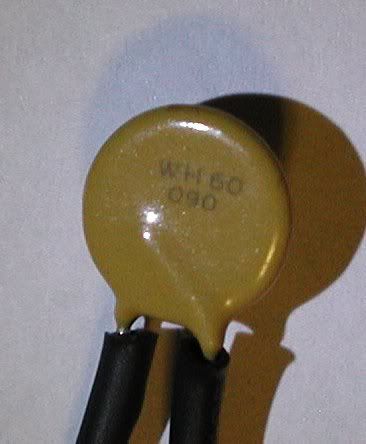 Here is what the circuit appears to be: 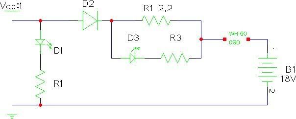 (Oops: I notice I have two R1's in there  ) And finally, here's the component side of the circuit board: 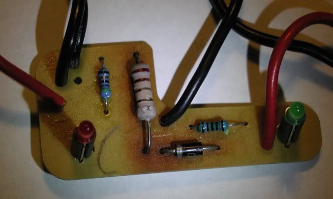 The diode may be labelled 1N100 - that's a standard 400mA 100V diode, apparently. Solder joints on the trace side of the PCB look good. Now here's what happens when I plug it in with a battery pack. The power LED (D1, green) comes on; the charge LED (D3, red) may come on. D2 - the 1N100 - and/or the current limiting resistor (2.2 ohm) start heating up. If the charge LED was on, it goes out. D2 becomes almost too hot to touch (not enough to burn, but pretty close). The battery does not charge. However, if I short out D2 - which, it appears, is only so the battery doesn't drive the power LED, D1 - the charge LED (D3) comes on and battery starts charging. Voltage across the battery in this case is about 21V. You can see in the PCB photo that the board around D1 and the big resistor (2nd "R1") is discoloured from the heat. From this, I suspect that D2 - the protection diode - has failed. It also could be, of course, that the adaptor's voltage is low. A distant third is that the 2nd "R1" has failed, although it tests at 2.2 ohms, which matches its markings, if I am reading it correctly. So, if I replace D2, would that be sufficient to get this working again? Or, in searching around, I found these two plans for chargers that should work, it appears, for 18V; would one of these be more appropriate: electronicdesign.com/Article/ArticleID/1823/1823.htmlweb.telia.com/~u43200663/power/charger.htmNote that my electronics skills are about the level of soldering together kits; there's no way I could design a circuit. (I do have some good electronics stores nearby, notably Sayal and Active Components - right next door to each other, no less, so there's no problem finding components.) I would appreciate it very much if someone could give me some help (or hints as to where I could find help), as it doesn't appear that there is a replacement charger available - and, in any event, if it's just the diode it's a lot cheaper to replace that rather than the whole thing. The drill, and charger, is a Jobmate from Canadian Tire, by the way; similar to this one. |
|
|
|
Post by Czero 101 on Nov 15, 2007 3:12:06 GMT -4
I don't know electronic components very well, BUT... I do know how to Google ;D It appears the the component you are unsure of is a "PPTC Resettable Fuse" which protects the circuit from being burnt out by a power supply overcurrent. Googling "wh60 090" brought me to this page: www.makesafer.com/En_ProductShow.asp?ArticleID=168which is a product line spec sheet for a certain manufacturer line of WH60 PPTC Resettable Fuses. Googling "PPTC Resettable Fuses" brought me to this page: www.globalspec.com/FeaturedProducts/Detail/RFEInternational/PPTC_Resettable_Fuse/18401/0which explains what the component is and how it works. As to the problem with the charger, I dunno... I think you might be onto something with the idea that the D2 protection diode might be shot. Replacing it seems logical, BUT..
please don't take my word for it. I am not an electrician by any means. I don't even play one on tv.  Cz |
|
|
|
Post by decados on Nov 15, 2007 5:14:42 GMT -4
On that large resistor, is that Red, Red GOLD, or Red Red Brown? I'm having a hard time seeing it.
I think your best bet is to replace the Diode D2. In electronics, GENERALLY, it's usually the fault of a semiconductor device as they tend to be more 'fragile' then things such as resistors.
Goes without saying, when you solder in the replacement, make sure you heat sink the leads of the diode. A small pair of needle nose pliers and some rubber bands around the handle will work just fine.
|
|
|
|
Post by Tanalia on Nov 15, 2007 7:01:31 GMT -4
On that large resistor, is that Red, Red GOLD, or Red Red Brown? I'm having a hard time seeing it. Gold should never appear in the 3rd stripe, only in the 4th (and/or the 5th on resistors with more than 4 stripes)
I agree that it sounds like the diode has gone bad. You should be able to check it by using your multimeter -- with power and battery unplugged, set it to measure resistance (or check continuity), with the probes connected to it one way it should look like a small resistance (or show a complete circuit), the other way should look like infinite resistance (or an open circuit). This isn't foolproof for this case, though, as it may only leak at a voltage higher than your meter uses; but if it shows low resistance both ways it's definitely bad. |
|
|
|
Post by grmcdorman on Nov 15, 2007 11:33:35 GMT -4
Czero 101: Thanks. I tried searching for it with the space; I didn't think of taking out the space. I think you've got it; it makes sense based on the circuit and the way it's attached (presumably it's because it gets hot when it "trips"). The diode shows very high resistance one way, and low the other, so that's not definitive. I don't recall the exact values (I'm at work); I also measured the voltage across it under load; again, I don't recall the value but it wasn't very high. ETA: According to this source, for a four-band resistor the third band can indeed be gold. In this case, I'm pretty sure it is. Certainly it does measure at 2.2 ohms.
|
|
|
|
Post by decados on Nov 15, 2007 19:05:52 GMT -4
Standard multimeters sometimes aren't the best at testing a diode. If you're just doing a standard resistance test, a multimeter uses a very low voltage to test resistances and sometimes that isn't enough voltage to overcome the forward voltage threshold of the diode.
Some modern multimeters have a specific diode test function that is preferable to use. Also, it can be difficult to test individual components in a circuit when they're still in the circuit. Unsolder one lead of the diode and run your test again.
|
|
|
|
Post by grmcdorman on Nov 15, 2007 22:17:43 GMT -4
Standard multimeters sometimes aren't the best at testing a diode. If you're just doing a standard resistance test, a multimeter uses a very low voltage to test resistances and sometimes that isn't enough voltage to overcome the forward voltage threshold of the diode. Some modern multimeters have a specific diode test function that is preferable to use. Also, it can be difficult to test individual components in a circuit when they're still in the circuit. Unsolder one lead of the diode and run your test again. My DMM does have such a function, although I'm not terribly conversant with that function. As to isolating it in the circuit, if you look at the diagram you'll see that, if neither the battery to charge nor the power supply are connected, the circuit portions on either side of the diode are isolated - so it shouldn't be necessary to physically remove it. The diode test (also continuity) function of my DMM reports continuity in the forward direction, and open circuit in the reverse, for the diode in question. There's also a numerical display, which reads 550 in the forward direction, but I have no idea what it means; it's not ohms. (Open circuit is 1525). The DMM is a Beckman Industrial DM78 (also sold as CircuitMate); unfortunately I've lost the manual. |
|
|
|
Post by Tanalia on Nov 15, 2007 23:45:25 GMT -4
ETA: According to this source, for a four-band resistor the third band can indeed be gold. In this case, I'm pretty sure it is. Certainly it does measure at 2.2 ohms. Ok, I don't remember it that way, and the chart I double-checked against must have been old too  |
|
|
|
Post by dumbtechie on Nov 16, 2007 0:13:41 GMT -4
On that large resistor, is that Red, Red GOLD, or Red Red Brown? I'm having a hard time seeing it. Gold should never appear in the 3rd stripe, only in the 4th (and/or the 5th on resistors with more than 4 stripes) This is incorrect. When used as the 4th band on a resistor which is specified to only 2 significant figures (all 5% and 10% types), gold and silver indicate tolerance- gold= 5%, silver= 10%. The third band is the multiplier. When used in the position where the multiplier band should be, gold= x0.1, silver= x0.01. So, a resistor marked red, red, gold, gold would be 2.2 ohms, 5%, like so: 1st band-red=2 2nd band-red=2 3rd band-gold= multiply by 0.1 (22 x 0.1=2.2) 4th band-gold= 5% tolerance. Most DMMs implement the ohmmeter function by causing a known current to flow through the resistance under test and measuring the voltage drop across it, e.g., if the test current is 1 mA and the voltage drop is 470 mV, the resistance is 470 ohms. The "550" most likely means that the forward voltage drop of the diode is 550 mV at the test current for that DMM range- a not unexpected reading for an Si diode. The symptoms here are somewhat contradictory. What causes the "charging" LED to light up is the voltage drop produced across the current limiting resistor R1 by the charging current flowing into the battery. Red LEDs usually have a forward voltage of 1.6-1.8V at normal operating current, which implies that about 800 mA has to flow into the battery to light up the LED. (that PTC device is rated for a normal carrying current of 900 mA and a trip current of 1.8A, so that seems about right.) Overheating of the 2.2 ohm resistor implies excessive current passing through it, while the charging LED going out implies low or no current passing through the 2.2 ohm R- see the contradiction? If the diode shows a respectable front/back ratio when you buzz it out, which it apparently does, it's probably not failed. Silicon diodes usually fail either shorted or open (more commonly shorted), which would be obvious on an ohmmeter test. A more subtle failure, like excessive reverse leakage current, probably wouldn't account for the charger's symptoms. 21V across the battery is about what I'd expect from a fully charged 18V Ni-Cd pack under charge. Since I can't check it out in person (I'd be curious about the voltage coming from the wallblob, across the battery contacts with the battery in and out of circuit and the voltage drops across some of the other components when it's messing up, as well as whether the wallblob is a simple unregulated DC-out blob or has voltage regulation or current limiting or even charge termination circuitry), I'll throw out a hunch: Your battery pack may be starting to poot. That's just a hunch though. This is a real "I'd have to see it" situation. |
|
|
|
Post by grmcdorman on Nov 16, 2007 11:17:16 GMT -4
dumbtechie, I see your point about the contradiction w.r.t. to the heating up. If I recall correctly, the voltage across the charge LED/resistor network was about 1.3V, and about 0.5V across the diode. I'll check on these and other voltages this evening.
Perhaps it's not current that's too low, but voltage? (Of course, then the question is, if there is current, where's it going when the battery isn't charging? ... and why does the battery charge if the diode is shorted out?) It's very ... odd.
With respect to the battery pack: I have two. Both show the same symptoms, which makes it less likely that it's the battery pack failing (although not impossible of course).
The "wallblob", as you call it (I've also heard "wall wart") is a sealed package, so I can't tell what's inside it. Unfortunately, I don't have any other 25VDC source to try.
ETA: I was thinking maybe the resistor has failed - i.e. its resistance is a tad too high - but it does measure at 2.2 ohms (although the LED in parallel may throw that off).
ETA 2: A google search on the cordless drill brand turned up a few cases where the charger, reportedly, had failed - at least according to the posters. The suggestion there was to buy a new drill, so one would have two drills and (in this case) at least three battery packs. However, if it's just one of the components in the charger that failed, it's much cheaper to fix the charger.
|
|
|
|
Post by dumbtechie on Nov 16, 2007 15:28:51 GMT -4
Curiouser and curiouser. 1.3V across a 2.2 ohm resistor will dissipate about 0.768W in the resistor. From its size and appearance it's most likely a 1W or 2W metal-oxide type; based on the current that would be required to light the LED and the current rating of the PTC device, more likely a 2W. In either case it should get somewhat hot but not damagingly so.
If the resistor reads within +- 5% of 2.2 ohms- anywhere from 2.09 to 2.31- it's within spec. I have seen resistors "cooked" off-value, but when that happens it's usually obviously out of tolerance. The odds are that the resistance ranges of your DVM don't produce a high enough maximum voltage to bias the LED into conduction, so you probably are getting a valid reading on the resistor. Even if the LED were shorted, there's a 47.0 ohm 1% resistor in series with it, which would produce an error of only -4.5% in measuring the 2.2 ohm resistor.
That diode is almost certainly not a 1N100- that's a germanium diode in a glass DO-7 package, used primarily in detector applications and not something you would be likely to find in a power supply or battery charger. The diode in your picture is in an epoxy DO-41 package, which is commonly used for GP Si rectifiers in the 1A IFAV class, e.g. the 1N4001-1N4007 series.
The reason I'm curious about the wallblob is that I would expect the charging circuitry for a power drill battery pack to be somewhat more sophisticated than what's on that PC board. While that circuit would work fine for simply pumping charge into the battery, once it's come up to full charge you need, to prevent damage, either to shut off the charging current altogether or reduce it to no more than 0.05*C (C= battery's rated capacity in amp-hours). Both of the charger circuits you linked to do that by monitoring the voltage across the battery and shutting off the current whenever the battery voltage is high enough to indicate full charge. There's nothing in the circuit you've traced on that PCB that could do that; all I see there is circuitry for short-circuit protection and indicating power and charging status.
Wallblobs can contain anything from the most basic transformer-rectifier-filter raw DC power supply to regulated switching power supplies with multiple output voltages- including battery charge control circuitry. In fact, one of our recent design and construction projects here at work uses a 6V sealed lead-acid battery to provide backup power for logic circuitry and relays; the charger for that battery is entirely contained in a wallblob. Some charging circuits use pulses of current, which could throw readings taken with a DC voltmeter badly off.
If you could post all of the markings on the wallblob it could be enlightening.
|
|
|
|
Post by grmcdorman on Nov 16, 2007 20:23:47 GMT -4
BINGO!
Measuring voltages, I got 0.5 mV (that's millivolts) across the R1/charge LED network when the charge LED was off.
Taking a closer look at the solder side of the PCB, the R1 does have a bad connection. I'll resolder it and see what happens.
The manual, by the way, says, quote "It is normal for the battery charger to hum and be warm to the touch during operation."
|
|
|
|
Post by grmcdorman on Nov 16, 2007 20:25:33 GMT -4
BINGO!
Measuring voltages, I got 0.5 mV (that's millivolts) across the R1/charge LED network when the charge LED was off.
Taking a closer look at the solder side of the PCB, the R1 does have a bad connection. I'll resolder it and see what happens.
The manual, by the way, says, quote "It is normal for the battery charger to hum and be warm to the touch during operation."
ETA: That's with the power connected and a battery under charge, of course.
|
|
|
|
Post by grmcdorman on Nov 16, 2007 21:28:45 GMT -4
Well, fixing the connection didn't help. The behaviour is pretty consistent now: cold, the charge LED comes on. After about 5 seconds or so, it fades out, and the voltage across R1/D3 is less than 1 mV.
Unplugging the battery and replacing it has no effect.
HOWEVER, now the diode test/continuity for D2 fails in both directions. So it pretty much looks like D2 has died.
Here's more details:
The drill is a Jobmate 18 V Cordless Drill, part 54-2891-8 (Canadian Tire).
Manual section on charging says normal charge time is about 3 hours, and "The red indicator light will come ON when the battery is properly inserted into the charger stand. If red indicator light does not come ON, check to make sure battery is inserted fully into the charger and the electrical outlet is "live"."
The "wallblob" plate:
CLASS 2 POWER UNITS [sic]
Manufactured on: 10/2004
TYPE/MODÈLE: JM-25U
INPUT/ENTREE: AC 120 V - 60 Hz
OUTPUT/SORTIE: DC 25 V - 500 mA [line between 25 V - 500 mA is solid line over dots, which IIRC means pulsed DC]
POLARITY: [standard graphic, indicating ext. of plug -, interior +]
CAUTION: Risk of electric shock. Dry location only.
Made in China
It's not sealed, but it uses Yet Another style of screw designed to frustrate the amateur which I don't have, so I can't open it.
Voltages:
Wallblob output, no load: DMM reads between 22.7 and 22.9 volts.
Battery (no load): 19.9V
Circuit, no battery under charge:
Input (wallblob connection): 20.6V
Battery connections: varies between 20.3 and 20.4V
Power LED: 2.2V
Power LED resistor: ~18.6V (and it gets quite uncomfortably warm to the touch)
Battery under charge, charge light on:
Input: no change
D2: 3.3V
R1/charge LED network: can't get a value, it stopped working before I could check
Battery under charge, charge light off:
Input: no change
D2: ~0.3V to ~0.5V
R1/charge LED network: 0.5 mV (that's millivolts - something wrong here!)
PPTC fuse: also in the millivolt range
Battery: 19.9V - i.e. battery's intrinsic voltage
Something clearly is amiss in the R1/charge LED network and/or D2.
Removing the wall power results in ~18V across D2, obviously driven by the battery.
Resistance measurments: R1 (that's the big current limiting resistor, not the power LED resistor): 2.2 ohms.
Across the charge LED, D3: 48 ohms
Across R3: 46 ohms
(In the latter case I tried reversing the DMM leads, on the assumption that it's using DC and any current through the LED would be directional).
|
|
|
|
Post by grmcdorman on Nov 16, 2007 21:34:17 GMT -4
The diode, D2, is labelled '1N??001' (the ?? is obscured by the PCB). So that's probably a 1N4001, based on dumbtechie's remarks. I'll remove it later to get the proper ID, and buy a replacement.
|
|
 )
)
